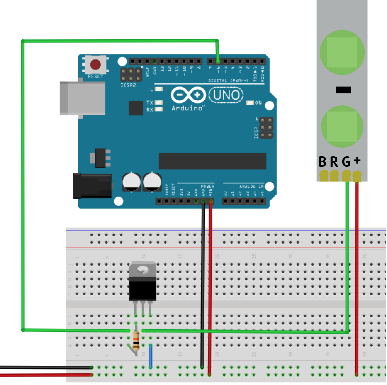
After a lot of errors and burnt boards, we redesigned our circuit. This one has been the most stable so far. It also keeps real cool 🙂

After a lot of errors and burnt boards, we redesigned our circuit. This one has been the most stable so far. It also keeps real cool 🙂
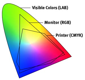
For the Carlson Garcia project, we were wondering about the possibilities of expanding the color vocabulary of the given 8 primary colors (RGB + complementaries) through PWM and code. Initially, we noticed that the screen values did not match the actual colors of the LED strips. It was a frustrating task to design sculptures that would display the actual colors that we envisioned. For this reason, we designed a processing application that would allow us to see how the screen colors were represented in the LED displays.
 We discovered that through PWM we could emulate a wide gamut of colors bigger than the given 8 primaries. However, the LEDs do not provide all the actual 255 values for each color. With the software and hardware like seen in the video, we are able to see how the colors will be shown in the LED hardware. This development has been very helpful to design sculptures with specific color palettes that we design. The color spectrum is not as wide as the 17 million colors of a screen, but at least we get to combine a wider number of colors. It is hard to know right now how many colors can be represented, but at least we have thousands of colors to chose from.
The code for our app is below (Processing with arduino firmata):
/* PALETTE for Processing 2.1.2 (2015)

Use Arduino Firmata to control ports. Cnange the index number [?] corresponding to your USB port

This program works with the hardware "palette" created by Carlson Garcia

www.carlsongarcia.com

Use nobs to mix RGB values of the LEDS. Record the liked colors by making screenshots

of the combinations */
import processing.serial.*;
import cc.arduino.*;
Arduino arduino;
int red1=3;
int green1 =5;
int blue1=6;
int red2=9;
int green2 =10;
int blue2=11;
int mapvalred1,mapvalred2;
int mapvalgreen1,mapvalgreen2;
int mapvalblue1,mapvalblue2;
boolean andruinoThere = true; //Deactivate andruidno for debuggings
void setup() {
size(800, 600);
println(Arduino.list());
arduino = new Arduino(this, Arduino.list()[12], 57600); // 3 or 12
}
void draw() {
background(0);
fill(mapvalred1,mapvalgreen1,mapvalblue1);
rect(0,0,width/2,height/2); //Left Rectangle
fill(mapvalred2,mapvalgreen2,mapvalblue2);
rect(width/2,0,width/2,height/2); //right rectangle
//rect(width/2,height/2,width/2,height/2);
//rect(0,height/2,width/2,height/2);
// read analog input arduino.analogRead(0) from potentiometer, store it in a variable, map it
// and write it arduino.analogWrite(9, mappedto255);
int valred1=arduino.analogRead(0);
int valgreen1=arduino.analogRead(1);
int valblue1=arduino.analogRead(2);
int valred2=arduino.analogRead(3);
int valgreen2=arduino.analogRead(4);
int valblue2=arduino.analogRead(5);
mapvalred1=int(map (valred1, 0,1023,0,255));
mapvalgreen1=int(map (valgreen1, 0,1023,0,255));
mapvalblue1=int(map (valblue1, 0,1023,0,255));
mapvalred2=int(map (valred2, 0,1023,0,255));
mapvalgreen2=int(map (valgreen2, 0,1023,0,255));
mapvalblue2=int(map (valblue2, 0,1023,0,255));
arduino.analogWrite(red1,mapvalred1);
arduino.analogWrite(green1,mapvalgreen1);
arduino.analogWrite(blue1,mapvalblue1);
arduino.analogWrite(red2,mapvalred2);
arduino.analogWrite(green2,mapvalgreen2);
arduino.analogWrite(blue2,mapvalblue2);
fill(255);
text(mapvalred1,width/4,400);
text(mapvalgreen1,width/4,420);
text(mapvalblue1,width/4,440);
text(mapvalred2,500,400);
text(mapvalgreen2,500,420);
text(mapvalblue2,500,440);
}
For the past couple of years, my friend and collaborator Aaron Zernack has been investigating audio synthesis using Current Voltage (CV/Gate) modular synthesizers. The whole thing has been very interesting to me aesthetically as sound, but also as to wonder about its potential in visualization. I have 2 modules now that allow me to experiment with analog synthesis in the visual realm. One is the Gieskes Oscillatoscope video synth and the other is the Minigorille Geometry Synth. Both of these devices have been an amazing ways of visualizing sound data and creating very exciting synesthesia art projects. However, I noticed that a lot of these synths use ATMega chips, same or similar to the arduinos. This made me think in a more conter-intuitive way. What if I could get rid of all the coding and produce synthesizers that modulate current voltage using simple electronics?

The diagram shows a snapshot of a circuit simulator of an LED fader using the 555 timer, resistors and capacitors. As you can see on the graphic we should have a smooth PWM modulation, but it ends up ramping up really fast. The video shows how the circuit is not really able to keep a consistent value, or a slow gradation of value at the least. Anyhow, This is mostly a new venue for research and experimentation. It would be really cool to simplify the circuits for my sculptures and not necessarily need to use I/0 boards for each sculpture. In this case you can see how the Red color fades in and then very suddenly it becomes white. I was hoping for a smoother transition, but nevertheless, very interesting.
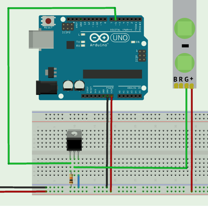
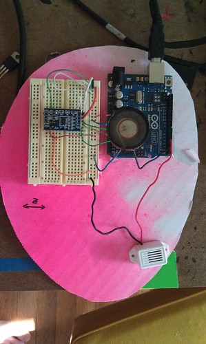
This is the circuit the right circuit to drive multiple RGB LED strips using the Arduino/wiring board. Resistor is 10Kohm and the transistor is a N-Channel MOSFET 60V 30A. Power is 12V @ 1A

I arrived to Sydney a few days ago for the ISEA. Before the conference starts on Tuesday, the event has a series of workshops with an electronic arts focus. I gave my workshop “Sensing for Visualization” yesterday and will repeat it today at 3 PM. The idea was to create a programming crash-course for physical computing. The workshop covered Processing and the Wiring board. It was cool to put the idea to a test with participants. The workshops occur at the College of Fine Arts of UNSW.
You can download the file with the workshop here
I was interested on teaching the Wiring board in the context of the Latin American Forum of the ISEA and to give information about this seminal project that preceded Arduino developed by the Colombian artist/designer Hernando Barragán. Hernando was a professor while I did my art undergrad in Bogotá at Universidad de los Andes, were he still teaches.
There are a lot cool things going on. Right now I at a workshop named SurSouth, an online collaborative conversation. It was great to reconnect with an old friend, Hamilton who now lives in London. His work is pretty cool. His objects are living organisms that exist through alchemy and technology. Check his stuff here
There we be a lot coming up. I’ll try to document other experiences of this trip. There is too much going on.

I have been involved with the band Tigerfox since their very beginnings as a sort of an art director for their live performances. Last year I did some video projections of computer programs with interactive graphics. For the their new music, my friend Ryan Puetz had this grandiose vision of adding lights to their show. I was excited to create some kind of “interactive light carpet” that I could control in the background, changing colors and rhythmic patterns. I used arduino and processing to make this. If you want to see a video of the performance/music, check here

Last January, I invited Camilo Martinez and Gabriel visited to visit the Lafayette area to develop an art workshop and residency with Purdue students and the lafayette community. It was a great experience to have this artists lead an arduino-based workshop aimed for the Physical Computing students from Purdue’s electronic and time based media artists.
During the workshop, Gabriel and Camilo taught us how to interface home appliances to email and twitter. The results were displayed in a one day exhibit at foamcity.
The Electronic Media Studio 1 is an art studio before it is a computer course. Our goal is to make art with computers, not simply learn how to use computers. Every student in this course should use it as an opportunity to become a media art creator rather than consumer. Assignments in this course are invitations to invent and experiment. They are also designed as hands-on experiences to explore the possibilities and pitfalls of this new medium.

int speakerPin = 2;

int buzzerPin = 4;

int buzzer2Pin = 0;

int xpin= A2;

int ypin= A1;

int zpin= A0;

int x, y, z;
void setup() {
// initialize the serial communication:
pinMode(xpin, INPUT);
pinMode(speakerPin, OUTPUT);
pinMode(buzzerPin, OUTPUT);
pinMode(buzzer2Pin, OUTPUT);
//Serial.begin(9600);
}
void loop() {
bass();
}
void beep (unsigned char speakerPin, int frequencyInHertz, long timeInMilliseconds) // the sound producing function
{
int x;
long delayAmount = (long)(1000000/frequencyInHertz);
long loopTime = (long)((timeInMilliseconds*1000)/(delayAmount*2));
for (x=0;x {
digitalWrite(speakerPin,HIGH);
delayMicroseconds(delayAmount);
digitalWrite(speakerPin,LOW);
delayMicroseconds(delayAmount);
}
}
void bass ()
{
x= analogRead(xpin);
y= analogRead(ypin);
z= analogRead(zpin);
beep(speakerPin,500+x,89);
beep(buzzerPin,90+y,80);
beep(speakerPin,290+z,x);
//beep(buzzer2Pin,700+z,10);
// beep(speakerPin,800+x,78);
//beep(speakerPin,x*0.7,sensorvalue%5);
//beep(speakerPin,xe*0.09,400); //
//delay(1000);
}
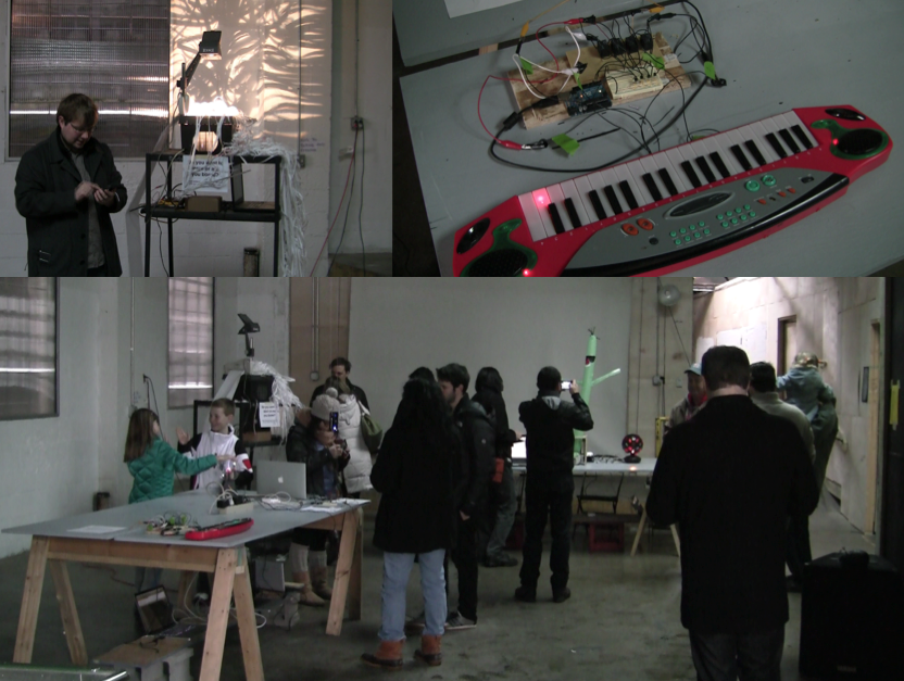
Last month, I met Nelu Lazar from an organization called Lafayettech. Nelu and his group have been organizing lots of community events in technology development and entrepreneurship. I was invited to do an Arduino workshop that was hosted in foamcity on June 3. It was really fun to find so many people interested in developments with arduino. In fact, I was the least knowledgeable person in arduino within the group. There were people of varied disciplines and ages, with a common interest. During the workshop, we were able to hack an accelerometer, a LED panel and some RGB lights. Here is a pic from that day.
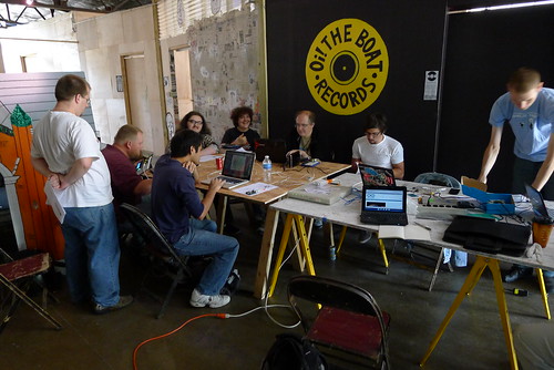
Also Nelu made the really cool video/interview about my project. (above)
Yesterday I presented in Dorkbot Indianapolis 0x8. It was a great experience and the Big Car service center provided a great venue for this event. I was recommended by my friend Mayowa Tomori who we knew from the radio chiguiro times. It was very cool to meet very interesting people and get feedback/ support for the type of work that I am doing. I guess it made me see my work in a more linear perspective and understand my process by having it explained to others. I mean… I think conversational speak is easier to explain art. Maybe I should do that in writing.Aaron, Paul and I rode down there for a little bit, ate great tacos at a place called “TEX MEX” and went to a house show. Anyways. I hope to be involved in more dorkbot events… Being part of this is a dream come true 🙂

In an effort to document and archive the circuit and program of the experiencia mistica installation, I publish this circuit and code, in wich a PIR (infrared motion sensor) triggers a display of a RGB LED strip and 2 strobe lights. Additionally has a 12V input and a webcam. It runs in processing with different libraries, such as Arduino, processing.video and minim for the audio
import processing.serial.*;

import cc.arduino.*;

import ddf.minim.*;

import processing.video.*;

import gifAnimation.*;

Minim minim;

AudioPlayer player;

Arduino arduino; //creates arduino object

Capture cam;

Gif tunel;
//variables for PIR

int PIRPIN = 2;

int ledPin = 13;

int counter;
//Variables for RGB strip
int REDPIN= 5;
int GREENPIN= 3;
int BLUEPIN= 6;
int r, g, b;
//Variables for R L strobes
int LEFTPIN =9;
int RIGHTPIN=10;
float leftChannel;
float rightChannel;
float soundValLeft;
float soundValRight;
void setup(){
size(800, 600);
colorMode(HSB);
tunel = new Gif(this, "tunel.gif");
tunel.loop();
cam = new Capture(this, 160, 120);
arduino = new Arduino(this, Arduino.list()[0], 57600);
arduino.pinMode(PIRPIN, Arduino.INPUT);
arduino.pinMode(ledPin, Arduino.OUTPUT);
arduino.pinMode(REDPIN, Arduino.OUTPUT);
arduino.pinMode(GREENPIN, Arduino.OUTPUT);
arduino.pinMode(BLUEPIN, Arduino.OUTPUT);
arduino.pinMode(LEFTPIN, Arduino.OUTPUT);
arduino.pinMode(RIGHTPIN, Arduino.OUTPUT);
minim = new Minim(this);
player = minim.loadFile("mystica2.aiff", 1024); //or 2048
player.play();
}
void draw(){
int pirVal = arduino.digitalRead(PIRPIN);
if(pirVal == Arduino.LOW){ //was motion detected
counter ++;
if (counter == 5){ // the sensor has to be triggered at least 5 times to detect strong motion
arduino.digitalWrite(ledPin, Arduino.HIGH);// send the siignal
player.play();
background (255, 0, 0);
//delay(2000);
}
}
if(pirVal == Arduino.HIGH){ //was motion detected
counter=0;
arduino.digitalWrite(ledPin,Arduino.LOW );
background (0, 0, 0);
}
if ( !player.isPlaying() ){
player.rewind();
}
if ( player.isPlaying() ){
for(int i = 0; i < player.bufferSize() - 1; i++) {
soundValLeft= player.left.get(i)*150;
soundValRight= player.right.get(i)*100;
}
int soundintL = int(soundValLeft); // int version of sound value
int soundintR = int(soundValRight);
arduino.analogWrite(LEFTPIN,soundintL);
arduino.analogWrite(RIGHTPIN,soundintR);
cam.read();
image(tunel,0,0);
image(cam, 322, 236);
if (g==255){ // loop for green variation
g=0;}else g++;
tint (g, 255, 255);
if (r==200){ // loop for red variation
r=0;}else r++;
arduino.analogWrite(GREENPIN,g);
arduino.analogWrite(REDPIN,r);
arduino.analogWrite(BLUEPIN,soundintR);
}
}
After reading a little bit about motion sensing with PIR sensors and arduino, I was able to improve this code a little bit. The idea came up from sensing “strong motion” as opposed to just a random one.

This image shows a previous code based on the buildr link above:
The idea is that it will only turn the led on or send a “motion detected” message if a strong motion is detected, that is if 5 consecutive signals from the infraRed sensor will trigger the actual action. I was trying to debug this sensor trying to understand its behavior correctly. When I built the circuit, I noticed the motion sensing was as not as reliable as I wanted. That was triggering a false or unwanted signal. Based on my observations of how my interactions with the sensor affected the LED and serial messages, I discovered that the sensor sometimes will send a weird “LOW” to the board and trigger the alarm… But what is the probability of 5 signals in a row? That is what this program does… It is very reliable now! It was just a software solution to the sensor debugging. In fact the “motion” sensor is actually activated by heat sensing, a variable associated with motion…. Watch out predator, I can sense you now!
int pirPin = 2; //digital 2

int ledPin = 13;

int counter;
void setup(){
pinMode(pirPin, INPUT);pinMode(ledPin, OUTPUT);

}
void loop(){

int pirVal = digitalRead(pirPin);
if(pirVal == LOW){ //was motion detected

counter ++;

if (counter == 5){ // the sensor has to be triggered at least 5 times to detect strong motion

digitalWrite(ledPin,HIGH);// send the signal put your trigger action here
}
}
if(pirVal == HIGH){ //was motion detected
counter=0;
digitalWrite(ledPin,LOW );
}
}

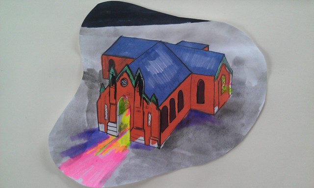
First sketch with the idea.
Okay, so I have embarked in a project that involves a lot of work, research and skill. A lot of people have seen me working at foamcity in a “church” or “castle”, but in reality is my Experiencia Mistica project. My motivation to do this project is an image that came to me a long time ago. This image is a three dimensional model of one of Lafayette’s churches. After that I started thinking about the most appropriate material to do a huge 3D model and after making 2 giant plywood structures in December, I went for plywood for this project. I have been obsessed with geometry for a while and during my PhD I’ve been exposed to visualization techniques and geometric modeling. I also teach a visualization class and Dr. Miller’s orthographic teachings came in very handy in the development of the model:
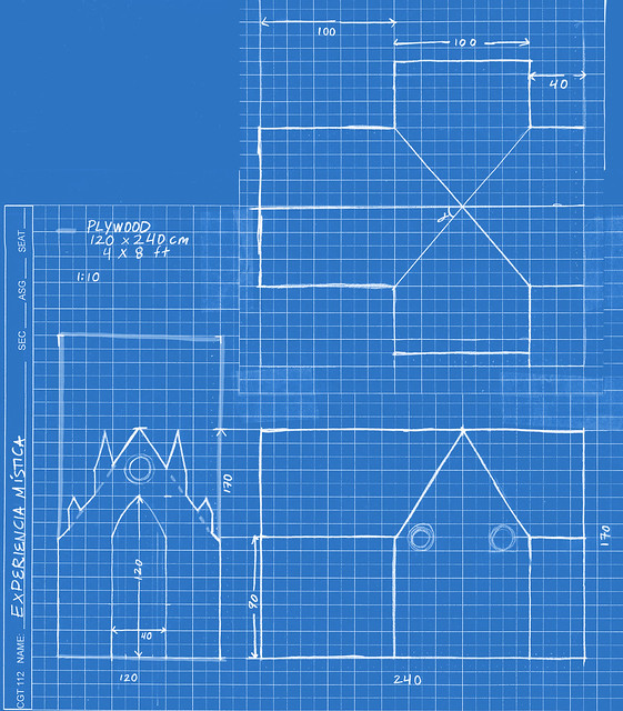
Max helped a ton with his knowledge and tools and we put together the main geometry in only 2 days! It was great. Now I am in the process of painting the outside and it’s been already a month of heavy work. This is how it looked last week:
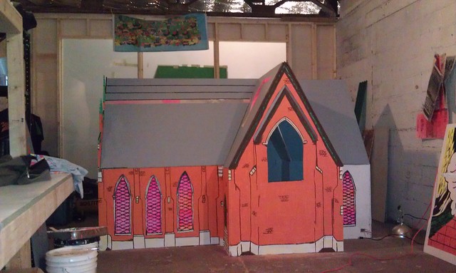
Since then I have repainted a lot of the early lines because I was not happy with the way the geometry looked kind of flimsy. The video on top shows a program for controling the lights inside via arduino. There is so much to be done!

1. Upload the “standardFirmata” example from the Arduino IDE in your Arduino board. If you are using Arduino UNO, there is a standard firmata for UNO.
2.Install Arduino library for processing in your libraries folder in the processing sketchbook
3.Test the following code for the Led blink to test that Arduino and processing are communicating correctly (code from the arduino playground page):
import processing.serial.*;

import cc.arduino.*;
Arduino arduino;

int ledPin = 13;
void setup()

{

//println(Arduino.list());

arduino = new Arduino(this, Arduino.list()[0], 57600);

arduino.pinMode(ledPin, Arduino.OUTPUT);

}
void draw()

{

arduino.digitalWrite(ledPin, Arduino.HIGH);

delay(1000);

arduino.digitalWrite(ledPin, Arduino.LOW);

delay(1000);      }
DEBUG.Try the analog read program in the arduino and use the serial monitor to see the maximum and minumum values of the accelerometer. You can take my word that they will be from 300 to 700. Supposedly should be (0-1023) in analog read with mid values around (500).
4. If the LED in the Arduino blinks it means that your “hello world” between the Arduino firmata and processing is working.
5.Build the circuit: (Connect to A0 for Y and A1 for X) in diagram it says 6 and 7, but it should be an analog pin.


import processing.serial.*;

import cc.arduino.*;

Arduino arduino; //creates arduino object

color back = color(64, 218, 255); //variables for the 2 colors

int xpin= 0;

int ypin= 1;

float value=0;

PImage a;

void setup() {

size(800, 600);

arduino = new Arduino(this, Arduino.list()[0], 57600); //sets up arduino

a = loadImage("mar.png");

arduino.pinMode(xpin, Arduino.INPUT);//setup pins to be input (A0 =0?)

arduino.pinMode(ypin, Arduino.INPUT);

}

void draw() {

background(back);

noStroke();

image(a,arduino.analogRead(xpin)-180, arduino.analogRead(ypin)-300); // in case you want to draw an image

//ellipse(arduino.analogRead(xpin)-130, arduino.analogRead(ypin)-130,30, 30); // in case you want an ellipse

}
–This program tracks down the X and Y values from the accelerometer and displays them altering the position of a graphic in the screen.
–You’ll need to replace the image mar.png in the data folder.
–The position of the object needs to be calibrated to the min and max values the accelerometer is giving you through the serial monitor and for this reason I substract 180 and 330 to the position of the graphic. It still needs improvement!
