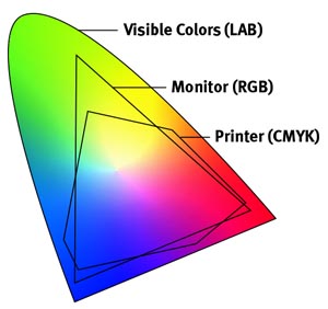
For the Carlson Garcia project, we were wondering about the possibilities of expanding the color vocabulary of the given 8 primary colors (RGB + complementaries) through PWM and code. Initially, we noticed that the screen values did not match the actual colors of the LED strips. It was a frustrating task to design sculptures that would display the actual colors that we envisioned. For this reason, we designed a processing application that would allow us to see how the screen colors were represented in the LED displays.
 We discovered that through PWM we could emulate a wide gamut of colors bigger than the given 8 primaries. However, the LEDs do not provide all the actual 255 values for each color. With the software and hardware like seen in the video, we are able to see how the colors will be shown in the LED hardware. This development has been very helpful to design sculptures with specific color palettes that we design. The color spectrum is not as wide as the 17 million colors of a screen, but at least we get to combine a wider number of colors. It is hard to know right now how many colors can be represented, but at least we have thousands of colors to chose from.
The code for our app is below (Processing with arduino firmata):
/* PALETTE for Processing 2.1.2 (2015)

Use Arduino Firmata to control ports. Cnange the index number [?] corresponding to your USB port

This program works with the hardware "palette" created by Carlson Garcia

www.carlsongarcia.com

Use nobs to mix RGB values of the LEDS. Record the liked colors by making screenshots

of the combinations */
import processing.serial.*;
import cc.arduino.*;
Arduino arduino;
int red1=3;
int green1 =5;
int blue1=6;
int red2=9;
int green2 =10;
int blue2=11;
int mapvalred1,mapvalred2;
int mapvalgreen1,mapvalgreen2;
int mapvalblue1,mapvalblue2;
boolean andruinoThere = true; //Deactivate andruidno for debuggings
void setup() {
size(800, 600);
println(Arduino.list());
arduino = new Arduino(this, Arduino.list()[12], 57600); // 3 or 12
}
void draw() {
background(0);
fill(mapvalred1,mapvalgreen1,mapvalblue1);
rect(0,0,width/2,height/2); //Left Rectangle
fill(mapvalred2,mapvalgreen2,mapvalblue2);
rect(width/2,0,width/2,height/2); //right rectangle
//rect(width/2,height/2,width/2,height/2);
//rect(0,height/2,width/2,height/2);
// read analog input arduino.analogRead(0) from potentiometer, store it in a variable, map it
// and write it arduino.analogWrite(9, mappedto255);
int valred1=arduino.analogRead(0);
int valgreen1=arduino.analogRead(1);
int valblue1=arduino.analogRead(2);
int valred2=arduino.analogRead(3);
int valgreen2=arduino.analogRead(4);
int valblue2=arduino.analogRead(5);
mapvalred1=int(map (valred1, 0,1023,0,255));
mapvalgreen1=int(map (valgreen1, 0,1023,0,255));
mapvalblue1=int(map (valblue1, 0,1023,0,255));
mapvalred2=int(map (valred2, 0,1023,0,255));
mapvalgreen2=int(map (valgreen2, 0,1023,0,255));
mapvalblue2=int(map (valblue2, 0,1023,0,255));
arduino.analogWrite(red1,mapvalred1);
arduino.analogWrite(green1,mapvalgreen1);
arduino.analogWrite(blue1,mapvalblue1);
arduino.analogWrite(red2,mapvalred2);
arduino.analogWrite(green2,mapvalgreen2);
arduino.analogWrite(blue2,mapvalblue2);
fill(255);
text(mapvalred1,width/4,400);
text(mapvalgreen1,width/4,420);
text(mapvalblue1,width/4,440);
text(mapvalred2,500,400);
text(mapvalgreen2,500,420);
text(mapvalblue2,500,440);
}
